Fire Flow Simulation in Water Distribution Systems
Simulating fire events in a water distribution system is a necessary part of any watermain design hydraulic report and it is often done to see how the system residual pressures are affected after the watermain being installed. I have seen several wrong or semi problematic approaches used in fire flow simulation therefore this post is mainly trying to show a more reasonable process. This is by no means “the way” to model fire simulation but it is the one that I think makes more sense from the hydraulics point of view. Please also note that this post is focused on modeling/numerical practices and not the fire flow test in the field.
Simulate Fire under Maximum Day Demand:
This is a very simple fact but I have seen lot of reports, which get it wrong. This is mainly required by fire standards. So do not use average day demand or peak hour demand with fire flow. The first one results in higher fire flow (i.e., higher pressure residuals) and the second one leads to much lower pressures.
Model the Fire Hydrant as an Orifice
There are two ways to model fire flow. The common approach is to add the fire flow demand to the node demand. Since you are most likely using EpaNET, InfoWater, or WaterGEMS therefore you are modeling the fire flow and the nodes pressure with demand driven approach. This means your hydraulic solver assumes that the demand is fixed and calculates the node pressures in the way that the required fire demand would be supplied, regardless of the residual pressure in the system. In other words, it will supply the demand even if the system pressure are very low or negative. This approach to estimate the fire flow is OK as long as the residual pressure in your system especially in the fire node is more than 15 m. As soon as the residual pressure approaches this limit, the results are less accurate and should not be trusted. Obviously, if you do not check the pressures in your system, you might assume that the system is capable of supplying the demand without realizing the fact that the model output is compromised due to low or negative pressures.
The more accurate approach is to simulate the fire flow as pressure dependent flow, which is more realistic.
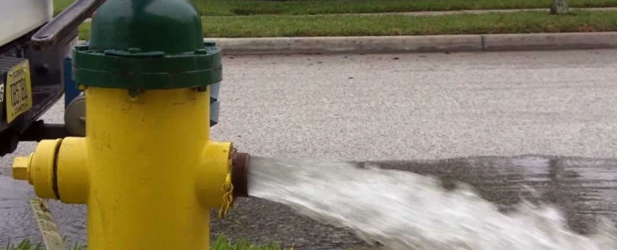
In reality, the flow from a hydrant depends on the pressure in that node. The higher the pressure, the higher the flow that could be expected. The hydrant flow could be modeled as flow through a nozzle or orifice which discharges to the atmosphere. This is the same as the Emitter flow concept in EpaNET. The flow for an orifice could be estimated using the following equation.
Q= αPβ
In which Q is the flow, α is the flow coefficient, β is pressure exponent and P is the pressure. For a flow from an orifice β = 0.5 which is mainly set by EpaNET globally. This means you set this coefficient for all of your nodes at once. The discharge coefficient, α, varies by the shape of the orifice and mainly published by the manufacturers. For a three inches hydrant port α is often equal to 12.5 lit/m-0.5 or 150 gpm/ft-0.5. If you are opening two ports this value should be doubled. Needless to say that this is a generalized number and should be used only as a starting point. You have to look at each hydrant manufacture specifications to find the exact number for the discharge coefficient values. This method could also be used to simulate the leakage from pipes albite with different coefficients. I will discuss how to model leakage using EpaNET or HydraCAL in future posts.
So to simulate the flow using orifice, you only have to set the α on the node that represents the hydrant location. EpaNET will calculate the maximum flow that could be provided in the hydrant location under a minimum pressure and it also, provides the actual residual pressure. Contrary to the first approach, this method would not result in a negative pressure in the location of the hydrant. If the estimated flow and the residual pressures in this approach are higher than your requirement then this is the maximum flow that you can get from your hydrant (without the pumper truck sucking the water out). If the flow is higher than your requirement but the pressure is lower, you have to model the fire flow as fixed demand to see how much pressure will remain. Although in this case, you are still able to pull the maximum calculated flow.
If both flow and residual pressure are lower than your requirement, this would be the most flow, that you can pull from your system and you have to change the system conditions (i.e., pumps in service or watermain diameters) to increase the flow and the pressure.
Check all of the nodes’ residual pressure in the zone
Be aware that the residual pressure in all of the nodes should remain above your fire pressure limit (i.e., 14 m or 20 psi in North America) not just for the fire hydrant location. When I say “all of the nodes”, I mean those that are at the same pressure zone where fire happens.
Which nodes should be selected for the fire simulation
Often people only consider the demand node with the highest elevation in the zone to simulate the fire flow. This is a good starting point and it is mainly based on the static pressure distribution! If you have a wide zone with a centralized supply system (i.e., there is a considerable distance between zone’s borders and the supply points) the dynamic head might be a more important variable in providing pressure at the zone’s borders. Therefore, the demand points that are far from the supply points should also be considered for fire simulation regardless of their elevation. Please note that a node might be physically close to the supply point but being supplied through a long/complicated set of watermains therefore be more sensitive to dynamic head variation and fire simulations. The best approach to simulate these systems is to use stochastic fire simulation and randomly choose and test the fire flow in most or all of the nodes.
How many simultaneous fire events to consider?
Often only one fire event is simulated for fire analysis but be aware that most of fire codes require increasing the number of simultaneous fire events based on the zone’s population. This means if you have a zone, which supplies more than a specific number of people you have to consider more than one fire flows at the same time. This kind of fire flow simulations are much more complicated and mainly requires stochastic simulation to find the critical locations. Whenever more than one fire event is simulated, choosing high elevation points or points that are far from the supply could result in misleading outcomes. I think, in this type of fire simulation, using stochastic event generators is necessary.
HydraCAL provides the full fire flow simulation package that helps you to evaluate your system performance under various fire conditions. This include using orifice to simulate the fire hydrants, and stochastic modeling of the fire locations or flow. It also provides you with the fire criticality map which show you how much fire flow could be supplied through the system at your required residual pressure. In the future posts I will write about specific fire simulation process in HydraCAL.
Extended Period Simulation vs Steady State
Extended period simulation or EPS is mainly used to simulate regular daily demands, (i.e., ADD or MDD). Fire events require specific control sets to change the system boundary conditions especially at the pump stations to satisfy the fire requirements. Therefore, it makes more sense to simulate fire under steady state condition at maximum day demand.
If you use steady state to simulate fire, keep in mind, although the flow and pressure at the hydrant location is critical for fire fighters, the sustainable supply of water is also important. Depending on the fire code that is being used, the system water supplies have to provide enough water for specific amount of time (i.e., 2~3 hours). If you are relaying on reservoirs flow, you have to watch them to make sure they have enough supply for the fire duration. Often the fire capacity is already included in the non-fluctuating portion of the reservoirs but it is still wise to watch their performance under fire events. Additionally, set the initial water level at the reservoirs to half of their non-fluctuating portion (i.e., 20%~30% of the reservoirs TWL). This is a conservative assumption to make sure that the system pressures are under worst water level at reservoirs.
In conclusion,
- Use maximum day demand with fire.
- Orifice flow is more accurate to simulate hydrants.
- Steady state modeling is easier to use and probably more correct than EPS for fire simulation.
- Be aware are of the number of fire events required for your system.
- Watch all of the nodes’ residual pressure.

